
## LED Bar Graph
The bar graph - a series of?LEDs?in a line, such as you see on an audio display - is a common hardware display for analog sensors. It's made up of a series of?LEDs?in a row, an analog input like a potentiometer, and a little code in between. You can buy multi-LED bar graph displays fairly cheaply, like?[this one](http://www.digikey.com/product-detail/en/MV54164/1080-1183-ND/2675674). This tutorial demonstrates how to control a series of?LEDs?in a row, but can be applied to any series of digital outputs.
This tutorial borrows from the?[For Loop and Arrays](https://www.arduino.cc/en/Tutorial/Loop)?tutorial as well as the?[Analog Input](https://www.arduino.cc/en/Tutorial/AnalogInput)?tutorial.

### **所需硬件**
* Arduino or Genuino Board
* LED bar graph display or 10?LEDs
* Potentiometer
* 10 220 ohm resistors
* hook-up wires
* breadboard
### **電路**
click the image to enlarge
[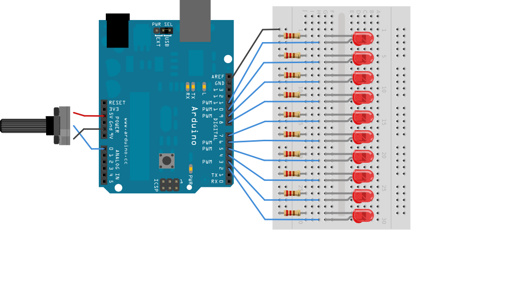](https://www.arduino.cc/en/uploads/Tutorial/BarGraph_bb.png)
image developed using?[Fritzing](http://www.fritzing.org/). For more circuit examples, see the?[Fritzing project page](http://fritzing.org/projects/)
Schematic:
click the image to enlarge
[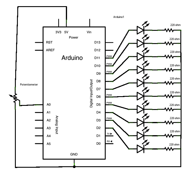](https://www.arduino.cc/en/uploads/Tutorial/BarGraph2_schem.png)
### **代碼**
The sketch works like this: first you read the input. You map the input value to the output range, in this case ten?LEDs. Then you set up a?[for loop](https://www.arduino.cc/en/Tutorial/Loop)?to iterate over the outputs. If the output's number in the series is lower than the mapped input range, you turn it on. If not, you turn it off.
/*
? LED bar graph
? Turns on a series of LEDs based on the value of an analog sensor.
? This is a simple way to make a bar graph display. Though this graph uses 10
? LEDs, you can use any number by changing the LED count and the pins in the
? array.
? This method can be used to control any series of digital outputs that depends
? on an analog input.
? The circuit:
? - LEDs from pins 2 through 11 to ground
? created 4 Sep 2010
? by Tom Igoe
? This example code is in the public domain.
? http://www.arduino.cc/en/Tutorial/BarGraph
*/
// these constants won't change:
const?int?analogPin?=?A0;???// the pin that the potentiometer is attached to
const?int?ledCount?=?10;?? ?// the number of LEDs in the bar graph
int?ledPins[]?=?{
??2,?3,?4,?5,?6,?7,?8,?9,?10,?11
};???// an array of pin numbers to which LEDs are attached
void?setup()?{
??// loop over the pin array and set them all to output:
??for?(int?thisLed?=?0;?thisLed??ledCount;?thisLed++)?{
? ??pinMode(ledPins[thisLed],?OUTPUT);
??}
}
void?loop()?{
??// read the potentiometer:
??int?sensorReading?=?analogRead(analogPin);
??// map the result to a range from 0 to the number of LEDs:
??int?ledLevel?=?map(sensorReading,?0,?1023,?0,?ledCount);
??// loop over the LED array:
??for?(int?thisLed?=?0;?thisLed??ledCount;?thisLed++)?{
? ??// if the array element's index is less than ledLevel,
? ??// turn the pin for this element on:
? ??if?(thisLed??ledLevel)?{
? ? ??digitalWrite(ledPins[thisLed],?HIGH);
? ??}
? ??// turn off all pins higher than the ledLevel:
? ??else?{
? ? ??digitalWrite(ledPins[thisLed],?LOW);
? ??}
??}
}
[[Get Code]](https://www.arduino.cc/en/Tutorial/BarGraph?action=sourceblock&num=1)
### **參考**:
* [pinMode](https://www.arduino.cc/en/Reference/PinMode)()
* [for](https://www.arduino.cc/en/Reference/For)()
* [digitalWrite](https://www.arduino.cc/en/Reference/DigitalWrite)()
* [if...else](https://www.arduino.cc/en/Reference/Else)
* [map](https://www.arduino.cc/en/Reference/Map)()
* [For Loop Iteration](https://www.arduino.cc/en/Tutorial/ForLoopIteration)?- Control multiple?LEDs?with a For Loop.
* [Arrays](https://www.arduino.cc/en/Tutorial/Arrays)?- a variation on the For Loop example that demonstrates how to use an array.
* [Row Column Scanning](https://www.arduino.cc/en/Tutorial/RowColumnScanning)?- how to control an 8x8 matrix of?LEDs.
- 說明
- 系統示例文件目錄結構及說明
- 01.Basics
- AnalogReadSerial
- BareMinimum
- Blink
- DigitalReadSerial
- Fade
- ReadAnalogVoltage
- 02.Digital
- BlinkWithoutDelay
- Button
- Debounce
- DigitalInputPullup
- StateChangeDetection
- toneKeyboard
- toneMelody
- toneMultiple
- tonePitchFollower
- 03.Analog
- AnalogInOutSerial
- AnalogInput
- AnalogWriteMega
- Calibration
- Fading
- Smoothing
- 04.Communication
- ASCIITable
- Dimmer
- Graph
- Midi
- MultiSerial
- PhysicalPixel
- ReadASCIIString
- SerialCallResponse
- SerialCallResponseASCII
- SerialEvent
- SerialPassthrough
- VirtualColorMixer
- 05.Control
- Arrays
- ForLoopIteration
- IfStatementConditional
- switchCase
- switchCase2
- WhileStatementConditional
- 06.Sensors
- ADXL3xx
- Knock
- Memsic2125
- Ping
- 07.Display
- barGraph
- RowColumnScanning
- 08.Strings
- CharacterAnalysis
- StringAdditionOperator
- StringAppendOperator
- StringCaseChanges
- StringCharacters
- StringComparisonOperators
- StringConstructors
- StringIndexOf
- StringLength
- StringLengthTrim
- StringReplace
- StringStartsWithEndsWith
- StringSubstring
- StringToInt
- 09.USB
- Keyboard
- KeyboardLogout
- KeyboardMessage
- KeyboardReprogram
- KeyboardSerial
- KeyboardAndMouseControl
- Mouse
- ButtonMouseControl
- JoystickMouseControl
- 10.StarterKit_BasicKit (與特定硬件相關,暫無)
- p02_SpaceshipInterface
- p03_LoveOMeter
- p04_ColorMixingLamp
- p05_ServoMoodIndicator
- p06_LightTheremin
- p07_Keyboard
- p08_DigitalHourglass
- p09_MotorizedPinwheel
- p10_Zoetrope
- p11_CrystalBall
- p12_KnockLock
- p13_TouchSensorLamp
- p14_TweakTheArduinoLogo
- p15_HackingButtons
- 11.ArduinoISP(暫無)
- ArduinoISP